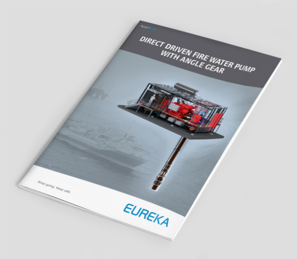
Diesel Electric FW System w/Submerged Electric Motor – General Pump Construction
General Pump Construction
The pump is a centrifugal type, heavy duty multistage design with end suction and designed according to API 610 for offshore application.
The pump unit is a radial split building block arrangement with one to six stages, with solid hub impellers. Both impeller and pump bowl are fitted with wear rings. The pump shaft is supported by sleeve bearings at every stage, which are lubricated by the pumped fluid (Sea Water).
To avoid water hammering during start up precautions should be taken both in design phase (Non return Valve, air release valve) and during operation (start up) of the equipment.
Pump bowls
The pump bowls are of the diffuser type. Each diffuser has an outlet flange screwed to the next diffuser or first riser column. Together with the riser columns and discharge bend on deck, they are designed for the required working pressure.
Riser columns
The riser columns bring the pumped fluid up to deck level. Each column is a flanged pipe and may be painted upon request. External anodes may be provided as protection of the caisson.
Nozzles
The discharge nozzle interface is a 150lbs to ANSI B16.5 flange raised face.
Pumps can be furnished with other flange ratings and facing upon request. Standard orientation is horizontal.
The pump inlet is protected by a strainer with openings equal to four times impeller eye.
As an option pumps can be delivered with a bucket around the pump unit, making it possible to connect the pump inlet to a pipeline.
Impeller
The impeller is single suction and designed with a large eye area to ensure low NPSH requirements and thus reduce the possibility of cavitations.
Casing wear rings
The casing wear rings are inserted in the pump bowl with a slight interference fit and secured with a hollow head setscrew.
Shaft sleeve
Shaft sleeves are keyed to prevent rotation and are axially secured between impellers and shaft lock nut. Thus securing the impellers in the correct axial position, as well as protecting the shaft from wear under the bearings in the pump unit.
Gaskets
O-ring type gaskets are provided between the pump bowls, column risers and deck head, which allows metal to metal assembly ensuring correct fit.
Non Return Valve
The pump may be equipped with a Non Return Valve located between the pump unit and the riser columns thus avoiding water hammering in discharge piping and to ensure the quickest possible supply of e.g. fire water.
Hypochlorite Injection
Fire Water Pumps may be equipped with a hypochlorite line for injection into pump suction to avoid marine growth in pump internals. The hypochlorite line will be terminated at the pump deck plate with 2” flanged 300lb RF connection. From the underside of the deck plate down to below electric motor will be executed in special chemical grade hose compatible with both injection fluid and seawater.
Diesel Electric FW w/Submerged Electric

