Diesel Engine
Diesel engines used in Eureka fire water systems are designed to operate in an offshore/marine environment. The diesel engine is skid mounted, coupled with the driven unit. For each project diesel engines are selected to meet the specified power requirements of the driven unit. The engines will normally run at 1500/1800 rpm depending on the application. The typical engine configuration consists of:
- Grey cast-iron crankcase with inspection ports
- Flywheel and flywheel housing
- Water cooled exhaust gas manifolds and turbo chargers
- Common-Rail fuel injection system with low and high pressure fuel pumps
- Closed crankcase ventilation system
- Dual starter system, electric, hydraulic, pneumatic, or any combination of these
- Engine driven coolant circulation pump and coolant thermostat for jacket coolant circuit
- Engine driven coolant circulation pump and coolant thermostat for charge air coolant circuit
- Integrated electronic engine control module (ECM) and monitoring system for:
- Engine speed control
- Engine monitoring and display of engine operating parameters and alarms
- Engine protection against critical operating parameters
- Automatic start sequence control
- Communication with external system, typically a Eureka PLC in the local control panel
- Safety shut-down override mode in Fire/Emergency/Essential mode
- Redundant ECM is available to comply with the requirements of NFPA 20
Exhaust system
The two diesel engine exhaust outlets are supplied with exhaust bellows to isolate vibration and absorb thermal expansion. Exhaust could be routed separately or joined with a Y piece to one common outlet.
Eureka offers various products for treatment of exhaust gases, all of which are sized and designed for the specific application and according to customer specifications. Products include:
- Silencer with spark arrestor designed to reduce the noise level to a required maximum.
- Exhaust cooler to reduce temperatures to a specified level, along with accessories including expansion tank for cooling liquid, circulation pump and pump motor.
Surface treatment Diesel Engine
Painting will be to engine manufacturer’s marine and offshore standard.
Cabling
The engine cabling is manufacturer standard cabling for offshore/marine environment, and as part of the type approval and cannot be altered. The cables are of flame retardant type.
Fuel system
The fuel system of the engine is typically comprised by a skid mounted switchable dual fuel pre-filter, with water separator and water-level sensor, a duplex fuel main filter and a high pressure pump to supply the common rail injection system. There are interfaces to a diesel day tank with one supply and one return line. The fuel return line is routed via a plate type heat exchanger to remove excess heat.
Lube oil system
The entire lube oil system is integral in the engine, cooled by the jacket water. The system ensures proper lubrication of the whole engine. Eureka normally includes a dual by-pass centrifugal filter in addition to the standard spin-on type filter elements configuration, for additional filtration of fine particles and by that increase the reliability. Oil level can be measured by means of a dip stick.
Combustion air inlet system
For air intake there are different solutions. There is the option of standard diesel engine manufacturer dry air filters mounted on the air intake of the engine, a setup used when the ambient air is used for combustion. More often Eureka will supply a custom combined air filter/silencer with interfaces for ducting for supply of combustion air from elsewhere on the installation. The filter/silencer will be in a material suitable for the application and according to customer specifications. For containerized solutions, the air filter is normally located inside the container, whereas with non-containerized solutions, the air filter is normally loose supplied.
One important safety measure of the diesel engine is the air flaps found on the air intake, to cut off air supply and shut off the diesel engine in case of over speed/presence of gas or other causes for emergency stops. The 24V power to the air flaps is derived from a source not affected by isolation of the system from the rest of the installation; to ensure the means for emergency stop are available should it be needed. The air flaps have a closed end switch feedback, and must be manually reset.
Cooling system
The engine has a 2-circuit cooling system. There is one circuit for charge air cooling and one jacket water circuit for cooling of the engine block, both of which are circulated by an engine driven mechanical pump. To remove the heat from the system, an external means of cooling is required. This is typically a skid-mounted plate heat exchanger. To compensate for thermal expansion of the cooling liquid, Eureka supplies expansion tanks, equipped with level switches for monitoring.
Eureka recommend a pre-heating arrangement for the diesel engine. The purpose of pre-heating is to maintain an even temperature to reduce wear during start up with low ambient temperature.
This consists of a skid-mounted pump, motor and heater, suitably sized for the total volume of the cooling system. The heater is equipped with thermostats for control and shutdown.
Generator
The generators used are 3-phase asynchronous type, designed for use in offshore/marine environment, in compliance with IEC60034. Voltages are standard 690V or 6,6kV, other voltages may be offered upon request. We deliver generators in a wide range of power outputs, decided individually per project to suit the driver and application. The generator is dependent on external cooling. This is most commonly achieved by use of seawater, either directly to a titanium cooler in the generator, or indirectly through a plate heat exchanger with a closed loop water/glycol system. The closed loop system requires an additional circulation pump powered by the generator . The sea water is derived from the fire water pump. Painting and surface treatment will be to generator manufacturer’s marine and offshore standard.
Available accessories for the generator include:
- AVR, single or dual
- CT’s and VT’s for protection and monitoring
- PT 100 in stator windings for winding temperature monitoring, 2 x PT 100 in each bearing for bearing temperature monitoring, PT100 before and after cooler, installed with 4-20mA Smart transmitters, HART compatible
- Vibration accelerometers in x, y directions for both DE and NDE bearings
- Anti-condensation heater
Control Panel
Control panels for the fire water package contain all components and functions necessary for self contained operation, monitoring and protection of the system. The main components typically included in the cabinet are batteries used to power the control panel in case of loss of power from the installation, battery chargers, generator protection equipment, a touch panel in the door to operate and monitor the system locally, and a PLC. The make of PLC can be altered from the Eureka standard to adapt to the SAS system of the installation. Cabinets are IP55 as standard. Minimum size of the control cabinet is (WxLxH) 1600x800x2000mm.
Transformer
To ensure the system is self-contained, transformers are in some cases required. This could be necessary to run auxiliary equipment such as coolant circulation pumps, radiators etc. needed to maintain safe operation of the equipment. Primary power will be derived from the generator set, secondary voltage is normally 690V. For every project the transformers are calculated and sized to minimize dimensions and weight, based on the required power by auxiliaries. Material, painting and enclosure will be designed to satisfy customer requirements.
Diesel Tank
Diesel day tanks are specially designed for each project, and can even be tailored for each single diesel engine system if this is required by space limitations, room or container configurations etc.
The diesel day tank is typically equipped with:
- One off magnetic roller type level gauge
- Two off level transmitter, 4-20mA Smart type, HART compatible. Capillary type may be provided upon request
- Manhole
- Typical nozzles for interface (Flanges type ASME B16,5 150# RF):
- Fuel filling from installation
- Fuel supply to diesel engine
- Fuel return from diesel engine
- Black start fuel supply to diesel engine, if required
- Tank drain
- Vent suitably sized
- Fuel overflow
Exhaust Cooling
Where there is a requirement of maximum temperature of the exhaust gas, Eureka may supply exhaust coolers. The temperature of the exhaust gas from the diesel engine is normally 400-450degC, and the exhaust cooler typically decreases the temperature to below 200degC. The cooling circuit is normally closed loop water/glycol with an electrically driven circulation pump powered by the generator.
The exhaust cooler is equipped with separate connection points for differential pressure and temperature transmitters, and instruments may be ordered as an option.
Sea Water Harness
Skids for fire water pumps include a sea water harness, designed to meet the requirements of NFPA20. This is used to reduce pressure on the seawater used for cooling, taken from the pump outlet. The harness has one duty and one stand-by line. The duty line includes an air operated valve, controlled by the local control panel, with position switches for monitoring. The valve is fail open for safety reasons, however it is normally closed during stand still to keep water in the cooling system, thus avoiding water hammer damage to heat exchangers or other pressure sensitive equipment in the cooling lines. There are also manual shut off valves for both the duty and stand-by lines. To avoid water carried contaminations, each line is equipped with a t-strainer.
Heat Exchangers
Eureka use plate type heat exchangers to cool down the diesel engine, fuel return, exhaust cooler and generator (generator can also be directly cooled by sea water). Heat exchangers are designed for each project individually to optimize size versus cooling effect. We generally use titanium plate exchangers, as cooling medium is sea water.
Room Cooler
To remove excess heat from the container/room, room cooler can be supplied by Eureka. For the self contained systems room coolers must be included. Room coolers typically consist of seawater cooled circuit, and electrically driven fans for air flow through the cooler. Hydraulically driven fans may be supplied as an option.
Piping
All on-skid piping will follow Norsok piping specification.
Pump and motor
1.0 – INTRODUCTION
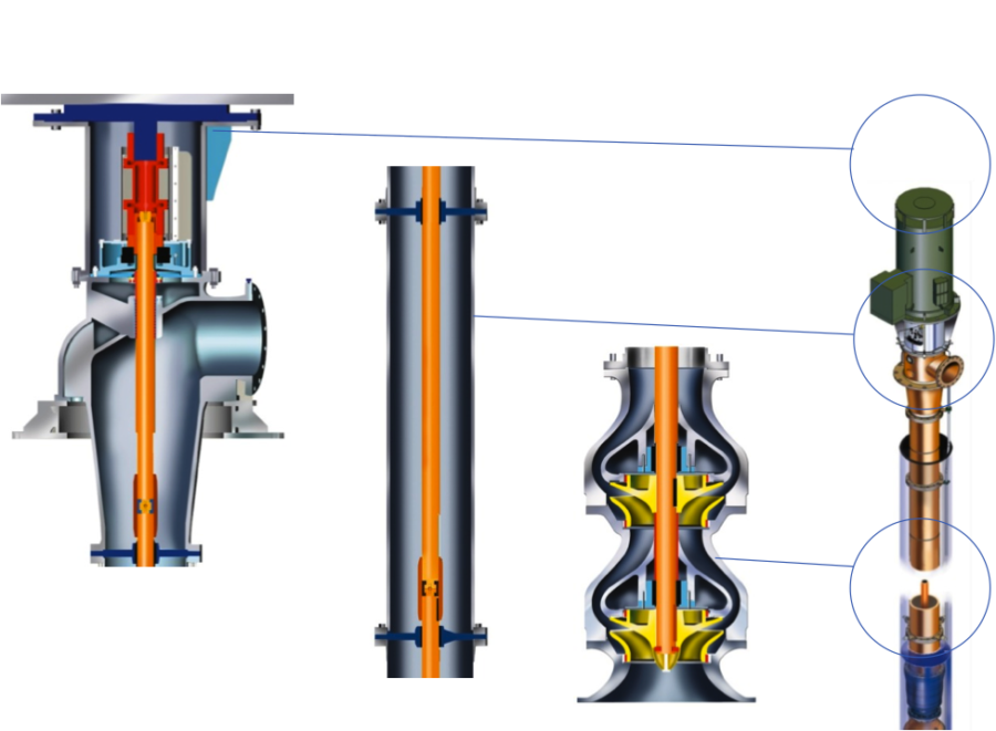
The pump unit is a radial split building block arrangement with one to six stages, with solid hub impellers. Both impeller (as an option) and pump bowl can be fitted with wear rings. The pump shaft is supported by sleeve bearings at every stage, which are lubricated by the pumped fluid.
The Pump unit is driven by deck mounted driver. Drive shaft is sectionalized, enclosed in the riser column and supported at the flange connections by spider bearings. Pump axial thrust taken by deck head mounted thrust bearing or by bearing in the driver. Oil or grease lubricated anti friction thrust bearing is used.
Mechanical seal or labyrinth seal with back up seal arrangement fitted at deck head.
Pump drive is through a spacer coupling to facilitate easy replacement of seals and thrust bearing.
Heavy duty motor pedestal flanged to pump deck head and fitted with ample access openings to spacer coupling, thrust bearing and seals.
Non sparking coupling protection (option) and easily removable for coupling inspection.
2.0 – CONSTRUCTION
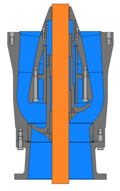
2.1 Pump bowls
The pump bowls are of the diffusor type. Each diffusor has an outlet flange screwed to the next diffusor or first riser column. Together with the riser columns and discharge bend on deck, they are designed for the required working pressure.
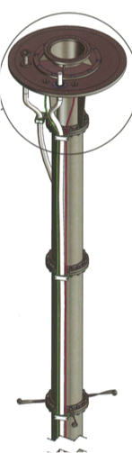
2.2 Riser columns
The riser columns bring the pumped fluid up to deck level. Each column is a flanged pipe, which supports the shaft journal bearings through spider bearings at each flange connection.
2.3 Nozzles
As standard discharge nozzle is supplied with a 150 lbs ANSI B16.5 flange with a 1/16″ raised face.
Pumps can be furnished with other flange ratings and facing upon request. Standard orientation is horizontal.
Suction nozzle is normally submerged into a basin or fluid filled caisson. As an option pumps can be delivered with a bucket around the pump unit, making it possible to connect the pump inlet to a pipeline.
2.4 Dynamic seal
A mechanical seal or labyrinth seal with back up seal arrangement are fitted in deck head (discharge bend). Mechanical seals can be either single or double.
2.5 Shaft
The shaft which is machined and ground to required dimensions, is of ample size to transmit the required power and prevent excessive deflection.
Long shaft pumps have the drive shaft enclosed in the riser columns. Several intermediate shafts connected by sleeve couplings, transmit power to the pump unit. Each shaft is normally two times the column section length. This means that each shaft is supported by two journal bearings. As an option, shaft length can be made equal to column length if the dismantling height on deck is limited.
2.6 Impeller
The impeller is single suction and designed with a large eye area to ensure low NPSH requirements and thus reduce the possibility of cavitations.
2.7
2.8 Casing wear rings
The casing wear rings are inserted in the pump bowl with a slight interference fit and secured with a hollow head setscrew.
2.9 Throat bushing
Long shaft pumps have a throat bushing fitted in the deck head to minimize leakage around the shaft. This can be a straight sleeve or a labyrinth seal. Both solutions ensure low pressure on the back up seal or mechanical seal.
2.10 Shaft sleeve
Shaft sleeves are keyed to prevent rotation and are axially secured between impellers and shaft lock nut. Thus securing the impellers in the correct axial position, as well as protecting the shaft from wear under the bearings in the pump unit. As an option, the intermediate shafts can also be delivered with protective sleeves under the journal bearings in the riser.
2.11 Gaskets
O-ring type gaskets are provided between the pump bowls, column risers and deck head, which allows metal to metal assembly ensuring correct fit.
2.12 Bearings
Long shaft pumps have axial thrust taken by a deck head mounted thrust bearing or by the bearing in the driver. Either oil or grease lubricated anti-friction thrust bearing is used.
Journal bearings in riser and pump unit are of the product lubricated sleeve type. Normally these bearings are of impregnated carbon with excellent dry running capabilities. Impregnation material and carbon/graphite quality will be dependent upon pump fluid.
2.13 Coupling
Pumps with an axial bearing fitted in the deck head will be furnished with a spacer type flexible coupling designed for easy mounting/dismounting.
If the axial bearing is located inside the driver, the coupling will be of a rigid axial adjustable type.
For both solutions a mechanical seal and/or bearing may be changed on site without dismounting the electric motor.
Fire Water Pumps may be equipped with a hypochlorite line for injection into pump suction to avoid marine growth in pump internals. The hypochlorite line will be terminated at the pump deck plate with 2” flanged 300lb RF connection. From the underside of the deck plate down to below electric motor will be executed in special chemical grade hose compatible with both injection fluid and seawater.
The pump may be equipped with a Non Return Valve located between the pump unit and the riser columns thus avoiding water hammering in discharge piping and to ensure the quickest possible supply of e.g. fire water.